
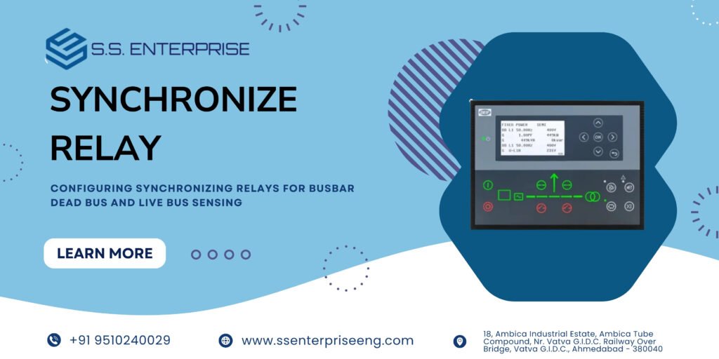
In a multi-genset power system, the synchronizing relay is the ultimate guardian of switchgear safety. Its primary job is to analyze the electrical conditions of an incoming generator and a common busbar, determining the exact moment it is safe to close the circuit breaker.
However, a synchronizing relay must handle two fundamentally different operational scenarios: connecting a generator to a completely unpowered (dead bus) or connecting it to an already energized (live bus).
Understanding how to configure synchronizing relays for both dead bus and live bus sensing is essential for every panel builder and switchgear engineer.
1. Dead Bus Closing Logic: Powering the System from Scratch
When a facility experiences a total blackout, all busbars are unpowered—a condition known as a dead bus.
How Dead Bus Sensing Works:
Voltage Threshold Detection: The synchronizing relay monitors the busbar potential transformers (PTs). If bus voltage drops below a pre-set threshold (typically 15% to 30% of nominal voltage), the relay recognizes the bus as “dead.”
First-On-Bus Logic: In a multi-generator setup, the system selects one designated generator (or the first unit to reach rated speed and voltage) to energize the dead bus.
Bypassing Phase Check: Because there is no existing electrical wave on the busbar to match, the relay temporarily disables its phase-angle and slip-frequency checks, sending an immediate “close permissive” signal to shut the generator breaker and energize the facility.
2. Live Bus Synchronization: Parallel Operation
Once the dead bus is energized, subsequent generators must be synchronized before joining the network. This is known as live bus synchronization.
How Live Bus Sensing Works:
Active Waveform Comparison: The relay detects that the bus voltage is above the live threshold. It now initiates active monitoring of three critical parameters:
Voltage Difference: Ensuring the incoming generator and bus voltages are within a tight tolerance (usually $\pm 1\%$ to $\pm 5\%$).
Slip Frequency: Calculating the slight speed difference between the two waveforms so they naturally drift into alignment.
Phase Angle Window: Issuing a breaker close command only when the phase difference drops to near zero degrees (typically within a 2 to 5-degree window).
Preventing Closing Shocks: Strict live bus configuration prevents out-of-phase synchronization, which would otherwise cause massive transient currents, sheared shafts, or catastrophic switchgear damage.
3. Best Practices for Programming Synchronizing Relays
Define Priority Rules: In multi-engine plants, program clear priority logic so that only one generator attempts a dead bus closure simultaneously, preventing racing conditions.
Test Dead Bus Timers: Ensure your relay’s dead bus timeout settings are calibrated correctly so the system doesn’t stall if utility power flickers during recovery.
Use Premium Hardware: Pair your control logic with precision-engineered components. Explore our high-grade Synchronize Relay and custom DG Synchronize Panel solutions to see how expert switchgear integration guarantees absolute safety.
Summary
Properly configuring synchronizing relays for both dead bus and live bus sensing ensures seamless transitions from total blackout recovery to stable, parallel multi-genset operation.
Elevate your switchgear safety with our precision Synchronize Relay modules and robust DG Synchronize Panel systems.