
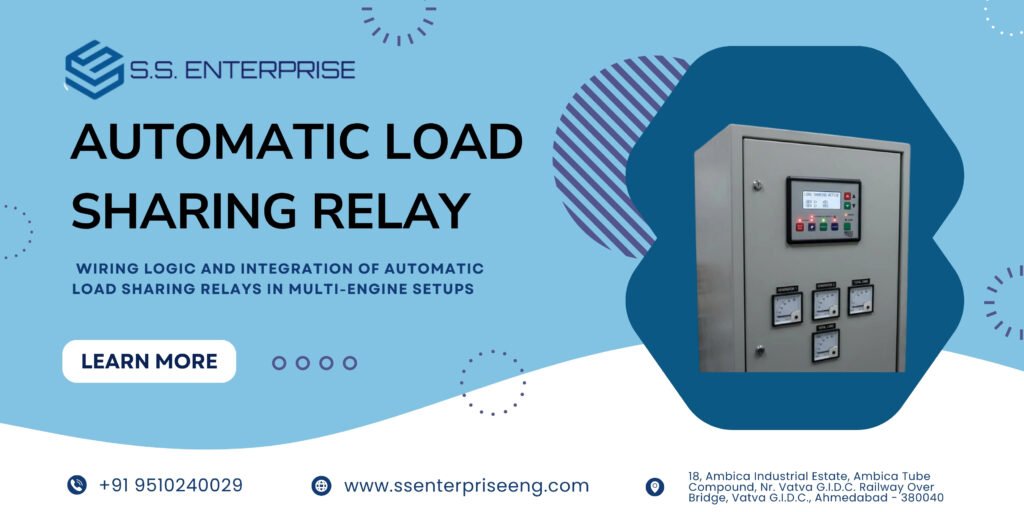
Running multiple diesel generators in parallel offers industrial plants the scalability and redundancy required to handle fluctuating heavy loads. However, simply connecting multiple generators to a common busbar is not enough. Without precise control, the units will fight for power, leading to severe imbalances, engine overloads, and unexpected system trips.
The key to harmonious multi-engine operation is the Automatic Load Sharing Relay. These intelligent modules manage active power distribution across all running gensets, ensuring each unit shoulders its fair share of the electrical burden.
Understanding the wiring logic and integration methodology for load-sharing relays is essential for any switchgear designer or panel builder.
1. Active Power (kW) vs. Reactive Power (kVAR) Sharing
Before diving into wiring architecture, it is important to distinguish between the two types of load sharing in a parallel system:
Active Power (kW) Sharing: Governed by the engine’s prime mover speed. If two generators run in parallel, their load-sharing relays communicate via a load-sharing line or digital CAN bus to adjust governor actuators, ensuring active power is divided proportionally based on engine capacity.
Reactive Power (kVAR) Sharing: Governed by the alternator’s excitation system. Voltage regulators adjust field excitation to ensure reactive power is balanced, preventing circulating currents between alternators.
2. Core Wiring Architecture for Load Sharing Relays
Integrating an automatic load sharing relay into a control panel requires precise wiring between the controller, the engine governor, and the switchgear circuit breaker.
A. Speed Governor Interface Wiring
Analog Control (0-10V or 4-20mA): The load-sharing relay outputs an analog control signal wired directly to the auxiliary input of the electronic speed governor. This signal raises or lowers engine RPM dynamically.
Digital CAN Bus Communication: Modern systems utilize digital communication lines (such as SAE J1939 or proprietary CAN protocols) to transmit speed reference commands directly to Electronic Control Units (ECUs) on modern diesel engines, drastically reducing physical wiring complexity.
B. Current Transformer (CT) Feedback Loop
To calculate real-time active power output, the load-sharing relay must monitor current from the alternator output:
Install dedicated metering Class CTs on each generator phase upstream of the circuit breaker.
Wire the secondary CT leads securely to the current inputs of the load-sharing module, ensuring correct polarity and phase matching.
C. Breaker Permissive and Interlock Wiring
The load-sharing relay acts as a gatekeeper for breaker operations:
Close Permissive: Once the incoming generator matches bus frequency, voltage, and phase angle, the relay sends a dry-contact “breaker close” permissive signal to the synchronizing breaker.
Load Control Relays: Auxiliary contacts are wired to handle soft loading and unloading ramps, preventing sudden load shocks when a generator joins or leaves the active bus.
3. Isochronous vs. Droop Control Modes
When configuring your load-sharing setup, choosing the right control mode is vital:
Isochronous Load Sharing: The preferred mode for parallel gensets. The load-sharing modules communicate continuously to maintain an absolute constant frequency while dividing the total kW load precisely according to engine ratings.
Droop Control: A traditional backup method where engine speed drops slightly as load increases, allowing natural load stabilization without communication lines, though with minor frequency variation.
For custom synchronization boards, pairing your system with a robust Automatic Load Sharing Relay ensures flawless load balancing across all operating conditions.
4. Best Practices for Panel Builders
Shielded Signal Cabling: Always use shielded twisted-pair cables for analog speed control lines and CAN bus communication to eliminate electromagnetic interference (EMI) from high-voltage power lines.
Rigorous Testing: Conduct secondary injection and simulated load tests before dispatching your switchgear. Explore our custom-engineered DG Synchronize Panel configurations to see how professional integration guarantees total reliability.
Summary
Proper wiring and configuration of automatic load sharing relays guarantee smooth, balanced operation in multi-genset systems. Investing in precise integration prevents engine overloads and protects your facility’s power infrastructure.
Upgrade your parallel power systems with our high-precision Automatic Load Sharing Relay and custom DG Synchronize Panel solutions.